Introduction:
In this tutorial series, we are going to see how to program an OLED display using any uController. I am saying 'any uController' because I am going to explain programming irrespective of uController used.
For simplicity, I am going to use Arduino Board for programming but the flow of programming and algorithm will be the same for other controllers like STM32, TivaC, ESP8266, ESP32 and any other uController with I2C bus compatibility.
Tutorials in this tutorial series Are as follows:
| Tutorial Name | What we learn? |
|---|---|
| 1) OLED Basic Programming | i) Basic of OLED ii) Power consumption iii) Pixel arrangement iv) Addressing modes of OLED v) I2C Registers and Commands vi) Writing First Program Sample Program: Drawing chess Board layout |
| 2) Using GLCD Font Creator For designing patterns on OLED |
i) What is GLCD Font Creator? ii) Create HEX code for a chess Board layout in GLCD Sample Program: i) Drawing chess Board layout designed in GLCD on 8x8 matrix ii) Drawing chess Board layout designed in GLCD on 16x16 matrix |
| 3) Adding custom font on OLED |
Create Hex code for a font in GLCD Sample Program: i) Displaying custom font on OLED created in GLCD |
| 4) Adding Indian languages |
Create Hex code for Devanagari Font Sample Program: Displaying Devanagari font on OLED |
| 5) Interfacing OLED display to FPGA |
Design a OLED driver for a low memory microcontroller. Sample Program: Displaying English and Devanagari font on OLED |
This is the first tutorial and as mentioned in the above table we are going to see
i) Basics of OLED
ii) Power consumption
iii) Pixel arrangement
iv) Addressing modes of OLED
We are not going to use any ready-made library (except library require for I2C communication which is provided by almost all controllers) so before programming, we should know some basic knowledge about OLED
please watch the following video:
please watch the following video:
i) Basics of OLED
In OLED displays, OLED(Organic Light Emitting Diode) is used. The main feature of OLED display is that it does not require a backlight. Hence we get good contrast in the OLED display.Also, it consumes less power. So this display is used in LOW POWER applications
In this tutorial series, we are going to use 0.96 inches 128x64 OLED display with SS1306 driver IC. 128x64 means it has 128 columns and 64 rows for pixels.
In this tutorial series, we are going to use 0.96 inches 128x64 OLED display with SS1306 driver IC. 128x64 means it has 128 columns and 64 rows for pixels.
 |
| image1: 0.96 inches 128x64 OLED display |
ii) Power Consumption
As mentioned above, OLED is used for Low power applications. Using SS1306 IC which is diver IC of our OLED display we can adjust contrast/brightness in 256 levels(0 to 255 ).OLED consumes power only for the number of pixels which are lighted hence power consumption highly depends on how many pixels you are using to display your text and also on brightness level.Let us see some observations done by me about the power consumption of OLED display.
Contrast = 255 (Full Brightness)
base current (all pixels OFF) = 350uA
iii) Pixel Arrangement
OLED Display Driver has Graphics Display Data RAM(GDDRAM) whose size is 128x64 i.e each bit in this RAM corresponds to each pixel on the display. If any bit is 1 then pixel corresponding to that will be glowing.
In the above image, we can see a 128x64 matrix of pixels. The whole matrix is vertically divided into 8 pages.
What is a page?
A page is a row of a collection of 8 verticle pixel. one page contains a matrix of 128x8 pixels
What is a page?
A page is a row of a collection of 8 verticle pixel. one page contains a matrix of 128x8 pixels
 |
| image3: Single page view |
8-bit data in Display RAM is displayed on verticle eight pixels. Bottom Pixel corresponds to MSB of the data and top Pixel corresponds to LSB of the data.
There are two pointers in the RAM to point the position on the display:
1) Column Address Pointer: (range: 0-127) pointer to 128 verticle columns
2) Page Address Pointer : (Range:0-7) pointer to 8 pages
using these two pointers we can display our data on any page and any column.
iv) Addressing Modes of OLED
There are three addressing Modes in OLED
1) Page Addressing Mode
2) Horizontal Addressing mode
3) Verticle Addressing Mode
We will concentrate on the first one, Page Addressing Mode only.
1) Page Addressing Mode
 |
| image4: Page Addressing Mode |
_____________________________________________________________
v) I2C Registers and Commands
Graphics Data RAM contains the data to be displayed. There are two registers, data register and Command register.Data Register: if we put data in this register, that data will be stored in RAM at the location pointed by Page Address Pointer and Column address pointer. So if we to display an 8-bit data on a column of 8 pixels, we first need to set page address and column address then we need to put data in the data register and then corresponding 8-pixel column will display our 8-bit data.
Command Register: For operations like setting page no. , setting column no., turning display ON/OFF. For such operation, we need to put the corresponding command in this command register. You can refer to SSD1306 datasheet for these commands.
vi) Writing The First Program
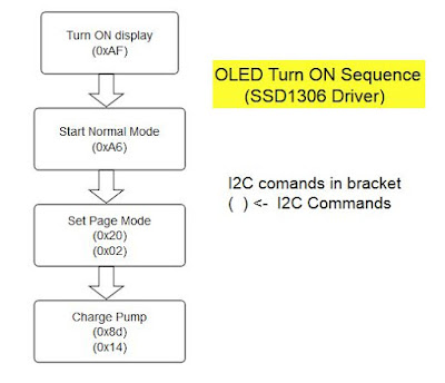
Following flowchart show the sequence of commands for initial setup of the OLED to turn it ON.
 |
| image5: OLED Turn On sequence |
Following flowchart showing the sequence of commands for setting X,Y cursor i.e to set column address pointer and Page Address pointer.
 |
| image6: Set X, Y cursor Sequence |
Circuit Diagram:
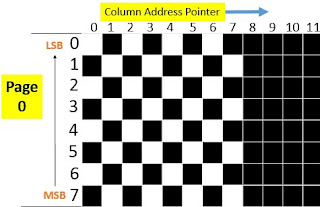
Following is an Arduino Program in which we turn on display then clear full display by writing 0x00 on all column and pages then we are sending data 10101010 (0xAA in HEX) to light 4 pixels in the first column then column address pointer will be automatically incremented by 1 Hence if we send 01010101(0x55 in HEX) again then new data will be displayed in next column on the same page. In code we are sending above two byte data to display chessboard layout on OLED display in Page0.
The expected output of Arduino code on display:
 |
| image7: expected output on the display |
Arduino Code:


Most of the time I don’t make comments on websites, but I'd like to say that this article really forced me to do so. Really nice post! transparent oled display buy
ReplyDelete